Found one of these.....
thrown out. It was dead and is a basic scope, but it has a battery power option and would be good to have as a "disposable" 'scope.
Opening it up and checking the supply voltages around the PCB revealed nothing surprising. Everything looked OK. The processor on the main PCB is a BGA packaged part. Taking a well educated guess I repowered the 'scope while pressing down on the processor, it worked :) so after applying foil around the chip and heating it with a hot air gun I had a working 'scope.
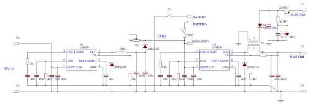
When I found the thing it was wet through which hadn't done the LiPo battery any good and it looked a bit 'puffy'. I have plenty of NiMh cells lying around so I thought I would make up a battery pack from these to replace the LiPo battery. First I checked the PSU to see what kind of provision had been made for charging the batteries....
The output stage of the PSU looks like this...
The battery is just connected across the output via the main switch.
The 'scope draws...
360mA, 8.4V, LCD Backlight.
380mA, 8.4V, Main board.
80mA, -8.4V, Main board.
After trying out a NiMh pack and realising it was stupid, I decided to dump the entire power supply and have the thing powered externally by a ready made 19 volt or so ( old laptop psu ) brick. Clearing out the power supply left lots of space. I can get lead acid batteries for free and there is room for a small one plus its charging psu plus all the other power stuff I am going to need.
While I'm modding this thing I might as well swap out that LCD backlight for an LED one, that will save 200mA !!!
This was easy to do :)
The replacement power supply is fed with 19V and provides 13.8V for charging the lead acid battery, this stage is followed by a further regulator which outputs +/-8.4V.
The backlight is powered from the 8.4V via two 47R paralleled resistors which gives it 20 to 30mA, which is plenty bright enough.
Wednesday, 6 July 2016
Metal Forge / Induction heater
YouTube suggested I watch this video.. Grant Thompspn - "The King of Random"
Ooo, thats good I thought. I'll make one. So I purchased some of the stuff to make this small charcoal fired forge, then remembered I was an electronics engineer and thought why am I not making an electric one? I pondered this for a while and then thought why am I not building an induction heated forge. So thats what I have started doing....
Induction heating involves inducing eddy currents in the work piece. These currents are big, so the work piece heats up.
Wikipedia has the explanation here https://en.wikipedia.org/wiki/Induction_heating
The output stage of this heater will probably connect to rectified mains so I would like all the control electronics isolated from this. I started with what I had 'in the drawer' to construct an oscillator and gate drive transformer driver. The IR2153 is a self oscillating half bridge driver, so sounded ideal for what I was trying out.
The board is supplied with 24V for the half bridge, regulated down to 12V for the IR2153. This provides a +/-12V square wave output to drive a gate drive transformer.
Out of curiosity I connected this...
...to the output of the driver via a 1uF Cap. Using a 'scope I could tune the IR2153 to get the coil resonating. This was able to heat my screwdriver up to above 100°C, I know this because my finger sizzled when I touched it.
From initial measurements on the above coil of wire I could tell the final coil would be conducting 100's of amps, so water cooling would be a good idea. I got some 8mm copper tubing and found a paint tin to wrap it around. I couldn't just wrap the tube around the tin, it would buckle at the first bend, so I perused the WWW and plenty of people suggested filling the tube with salt. This I did and the tube bent very nicely...
...Getting that salt out was difficult and took ages, tap tap tap, rotate, tap tap tap, rotate, Zzzzz
I tried buzzing it out with a sander and all sorts.
I needed a smaller coil. I wasn't going to use the salt method again. Water doesn't compress, so I capped one end of tube with a compression fit stop end, filled the tube with water and capped the remaining end. The tube requires a slight tweak to take up any air that got in, but after that the tube wrapped up into a coil nicely. Getting the water out was easy, just release the compression fittings and empty the water out. Using the compression fittings 'wastes' a couple of olives and some tube but saves a lot of time.
The coil gets hot without cooling, so I purchased a water CPU cooler from ebay. It was 'untested', but after cleaning it out, removing pipework and re-piping it to the coil, it pumped water round no problem.
The pump and cooling fan required an extra 12V supply, the pump at 200mA and the fan at 1.5A. I decided to under run the pump and fan at 10V and constructed a 2A buck regulator from a TL494 and associated components.
The heater as it was built was getting hard to work on so I put the lot into a metal enclosure..
I am planning on adding a 'wall' down the middle of the box to separate the electronics from the half that has water pumping round it, just in case :)
To test a theory about using Litz wire for the work coil I obtained some of these...
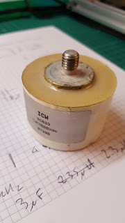
1uF, 1500V Polypropylene capacitors. Manufactured by ICW Ltd. I bolted three together to make 3uF...
Very nice.
Ooo, thats good I thought. I'll make one. So I purchased some of the stuff to make this small charcoal fired forge, then remembered I was an electronics engineer and thought why am I not making an electric one? I pondered this for a while and then thought why am I not building an induction heated forge. So thats what I have started doing....
Induction heating involves inducing eddy currents in the work piece. These currents are big, so the work piece heats up.
Wikipedia has the explanation here https://en.wikipedia.org/wiki/Induction_heating
The output stage of this heater will probably connect to rectified mains so I would like all the control electronics isolated from this. I started with what I had 'in the drawer' to construct an oscillator and gate drive transformer driver. The IR2153 is a self oscillating half bridge driver, so sounded ideal for what I was trying out.
 |
| IR2153 Half Bridge |
Out of curiosity I connected this...
...to the output of the driver via a 1uF Cap. Using a 'scope I could tune the IR2153 to get the coil resonating. This was able to heat my screwdriver up to above 100°C, I know this because my finger sizzled when I touched it.
From initial measurements on the above coil of wire I could tell the final coil would be conducting 100's of amps, so water cooling would be a good idea. I got some 8mm copper tubing and found a paint tin to wrap it around. I couldn't just wrap the tube around the tin, it would buckle at the first bend, so I perused the WWW and plenty of people suggested filling the tube with salt. This I did and the tube bent very nicely...
...Getting that salt out was difficult and took ages, tap tap tap, rotate, tap tap tap, rotate, Zzzzz
I tried buzzing it out with a sander and all sorts.
I needed a smaller coil. I wasn't going to use the salt method again. Water doesn't compress, so I capped one end of tube with a compression fit stop end, filled the tube with water and capped the remaining end. The tube requires a slight tweak to take up any air that got in, but after that the tube wrapped up into a coil nicely. Getting the water out was easy, just release the compression fittings and empty the water out. Using the compression fittings 'wastes' a couple of olives and some tube but saves a lot of time.
The coil gets hot without cooling, so I purchased a water CPU cooler from ebay. It was 'untested', but after cleaning it out, removing pipework and re-piping it to the coil, it pumped water round no problem.
The pump and cooling fan required an extra 12V supply, the pump at 200mA and the fan at 1.5A. I decided to under run the pump and fan at 10V and constructed a 2A buck regulator from a TL494 and associated components.
The heater as it was built was getting hard to work on so I put the lot into a metal enclosure..
I am planning on adding a 'wall' down the middle of the box to separate the electronics from the half that has water pumping round it, just in case :)
To test a theory about using Litz wire for the work coil I obtained some of these...
1uF, 1500V Polypropylene capacitors. Manufactured by ICW Ltd. I bolted three together to make 3uF...
Very nice.
Subscribe to:
Comments (Atom)


