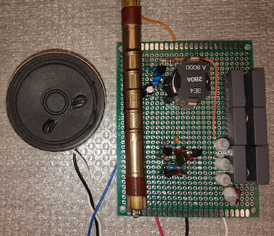
Crystal Radio
When I was a lad, I used to build radios. So I thought I would try and get the kids doing something else for 15 minutes that didn't involve those Vidiots on youtube.
You will often find diagrams on the internet using a single coil, paralleled with the tuning capacitor, directly connected to the detection diode and then earpiece. Although this will work, there will be very little selectivity in the tuning, since nothing will be impedance matched. The diagram of the radio I built is this...
And here is a quick description of each stage...
L1, L2 & L3 are wound on separate cardboard formers which can be moved up and down independently on a ferrite rod.
L1 is 20 turns, L2 is 40 turns and L3 is also 40 turns.
C1 is a 500pF air cored variable capacitor. In the picture it is ganged with other various capacitors, but it was the first one out the junk box that looked any good. You will notice one end of this is also earthed. This is because the capacitor has a metal frame and tuning shaft. It is this frame which is earthed to prevent my hand changing the resonant frequency of this part of the circuit while tuning.
D1 is an OA91 germanium diode, again out of the junk box. This diode must be a germanium diode, silicone diodes wont work. I have heard tale of Schottky diodes working here, but have yet to try it.
R1 is 100k. This is included here because the earpiece (SPK) I have is quite capacitive and so needs somewhere for the charge within it to dissipate. The earpiece is a high impedance ceramic type. The high impedance is important since there is very little energy available to drive any sort of passive load.
Some diagrams will include a capacitor across R1 to filter out the RF, but like I said, my earpiece is capacitive enough to do this job.
The aerial (ANT) was about 15 Meters of cable running from an upstairs window in the house to a tree opposite. The earth connection was to a copper radiator pipe. Many modern central heating systems are piped with plastic tubing, so this wouldn't work with those.
I initially had a 2 Meter metal stake hammered into the grass outside to provide the earth, forgetting that underneath the top foot of soil was just rubble and hardcore, not a good earth and not a good reception.
The tuning range of the radio was about 500kHz to 1.2MHz and me and the lad could tune in a couple of stations. There are another couple just above 1.2MHz so I'll have to do some adjustments to get them.
Selectivity of tuning was very good. The positions of L1, L2 & L3 on the ferrite rod didn't matter too much, as long as L1 was close to the other two windings. I will experiment a bit more with turns ratio but the next step will be tuning in those missing stations.
Obviously my son wanted it louder so we will probably be building an amplifier as well. This will need a battery. It is at this point I explained our radio didn't currently use any form of local power supply and the energy came out of the sky, that boggled his mind.


