Thursday, 6 September 2018

Inductance Meter

Quick Inductance Meter


I needed an inductance meter and had already spent my months spending money so I couldn't simply buy one.  I built one instead.

Luckily I had all the bits I would need to build the meter in the junk box.

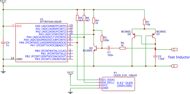
Inductance Meter Circuit

The circuit is very simple.  Just an LC oscillator with a known tank capacitor.  The micro counts the oscillator frequency and works out the connected inductance.

The formulae for the resonant frequency of the parallel LC tank is..

f = 1 / (2 * Pi * sqrt( L * C )) 

Rearranged for L is...

L = 1 / (4 * Pi * Pi) * C * ( f * f )

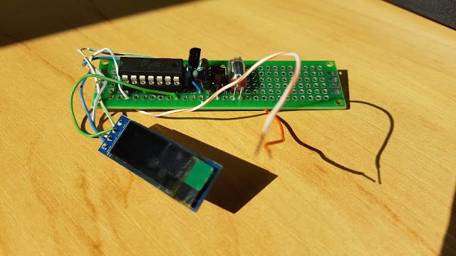
The circuit was cobbled together on a bit of board...

Inductance Meter Circuit

And a window, for the display, CNC'd into a plastic box.


Whoops, n00b, lol.
Clamp, clamp.
Then Clamp some more...


Fixed, nice label :)


I was stressing about powering the thing off a 1.5V battery, but I had a 9V battery and the case takes a 9V battery so I used an XC6202 3V linear regulator to power it.

I added a power button which briefly powers up the device, does a reading and then switches its self off after 10 seconds.

The circuit as built looks like this...

Schematic

Source code and hex file are available here
The meter measures from 1uH to 10mH.

And a quick video showing the operation.


Making that video put me over the budget for this quick project, I had to buy a holder for my camera.
Friday, 13 July 2018

Pressure activated speed controll

Controlling drill speed with pressure

I have a small hand held drill similar to a Dremel.


I need a way of controlling the speed of the drill while I am using it.

I thought some sort of pressure sensor mounted on the drill would allow me to vary the drill speed without needing an external speed controller.

To achieve this I used a piece of silicone pipe mounted on the drill which leads back to a pressure sensor, connected to a PWM power controller.

The pressure reading is taken by the PIC10F320 and converted to a PWM signal, which is connected to a MOSFET, which drives the drill.


Component choice is down to what I had to hand at the time.
Schematic


Wednesday, 28 March 2018

Wired Home Automation

After mucking around with the idea of wireless nodes around the house controlling various things, I dumped the idea and instead ran an RS485 network around the house.

So far I have two temperature and humidity nodes...


The hardware and software are really simple compared to any wireless solution.  These two nodes are polled every now and then and the average temperature in the house is calculated.  This will eventually switch the central heating on and off.

The 'controller' is simply a PC connected to the RS485 network via a bit of hardware.  The hardware does the automatic switching of the RS485 transceiver between Rx & Tx.  There is also a current limited regulator to provide 8V at 200mA.  All this is piped round the house through CAT5 cable.

The PC software is written in JavaScript and executed with node.js.  The user interface is via a browser on any capable device on the IP network.

The two temperature / humidity nodes were installed quickly and I soon required more nodes.  Hand building prototypes is fine but when more units were needed I did a PCB using EasyEDA and ordered them from JLCPCB.  Two weeks later, PCB's arrived.


Nice.  The PCB's were good quality and its not really worth etching boards at home anymore unless you need a PCB within the next few hours!

The PCB contains the RS485 comms stuff and a 5V regulator.  'Functionality' such as the temperature sensors can be added in the 'prototype' area.

The boiler and front house lights require a relay switch to operate them.  Rather than having a relay eating into the power budget of the system I used relays with a coil rated at 12V and ran them at 8V.  The circuit below was used to boost the voltage to the coil at switch on, reducing the coil voltage once it had switched.

Voltage boost relay driver

This circuit provides a voltage pulse of just under twice its supply voltage to the coil.  It also provides a turn off delay, determined by the charging of C1.


Friday, 23 March 2018

Stepper motor speed controller (Tesla coil winder)

I have been wanting to build a tesla coil forever, winding the coil has always put me off.  I think its about time I built one.

I was going to build the coil winder using a drill powered by a 300W, 0 - 40V variable voltage supply.  I built the supply using a variac and large torroid transformer.  The supply worked and is nearly indestructable, then I remembered I had some huge stepper motors...

...so I used those instead.

At least I now have another power supply :)

The stepper motor is driven by a microcontroller (ATtiny2313) with coils driven by mosfet's (BUK9840).  The speed and direction of rotation is varied using a rotary encoder.  The micro spits out information on speed / direction / revolutions on its UART.  The UART connects to an LCD.
The motor coils are rated for 3 volts.  To trade off some torque for speed the motor coils are driven from a 12V supply via some resistors.  These get quite warm in use, the only ones I had with a large enough power dissipation were 25W aluminium resistors, so no trouble there.


I was going to use a shift register to drive the LCD from a couple of pins, but didn't have any.  I have lots of ATtiny2313's so I stuck one on a board with the LCD and used the UART to shift data to the display.  The LCD microcontroller has a 32 character buffer into which any characters received on the UART are stored.  Characters below an ASCII space reset the buffer index to zero.


Very simple, now I've written the code for that it will be useful for other stuff.

To turn the piece of pipe which will be the secondary's former, I made two 'centers' out of the only stuff I had, concrete.  I used two plastic funnels for a mold, which also held the aluminium shaft central while the concrete went off.


Here, the bottom funnel is full of concrete and its stuffed into a bucket of sand while it sets.

The finished winder with first coil secondary.  The two blue concrete 'centres' are holding the piece of plastic pipe.


This only took about 15 minutes to wind, I was expecting to spend at least an hour on it.